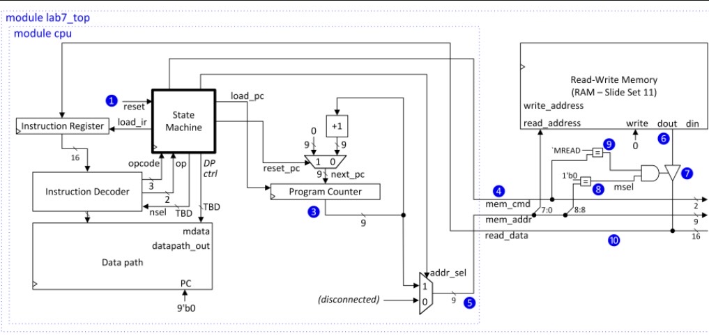
I separated the processor into a datapath and a multi-cycle controller. The controller decodes the instruction fields and generates the control signals required to move operands through the datapath over several clock cycles.
The datapath contains the register file, operand registers, shifter, ALU, result register, status logic, and the multiplexers used to select register addresses, immediate values, and write-back data.
Multi-Cycle FSM
Instructions move through a sequence of states so operand loading, execution, write-back, and flag updates occur on separate cycles.
16-Bit Data Path
Register values, operands, immediates, and ALU results are represented as 16-bit values.
Eight General Registers
The register file contains eight 16-bit registers with combinational read and synchronous write behavior.
N / V / Z Flags
The datapath tracks negative, signed overflow, and zero conditions for arithmetic and comparison operations.