Embedded Hardware | PCB Design

Rover Lighting Control System

I owned the lighting-controller subsystem for the rover electrical design team. I designed the custom PCB, developed the STM32 firmware and CAN interface, assembled five boards, completed hardware bring-up, and integrated the controllers into the rover.

Design Team Project Project Owner Completed
4-layer PCB
21-29.4 V input
5 boards assembled
STM32 + CAN control
1 A input fuse

From PCB Design to Rover Integration

I took the controller from schematic and PCB layout through assembly, bring-up, firmware development, CAN testing, and final integration on the rover.

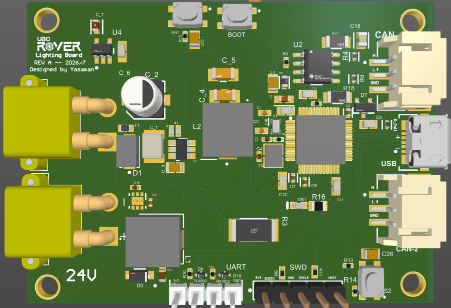
Component-side rover lighting PCB render
Component-side 3D render of the lighting controller.
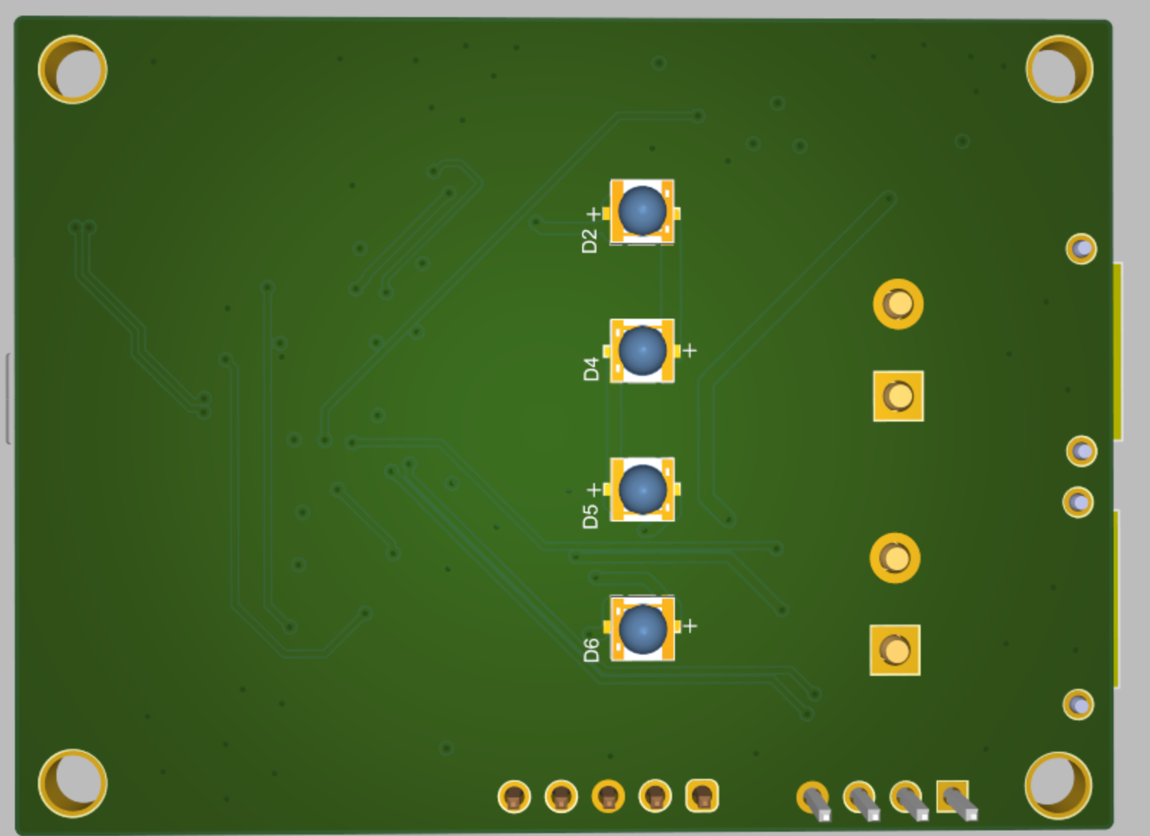
LED-side rover lighting PCB render
LED-side 3D render showing the four series LEDs.
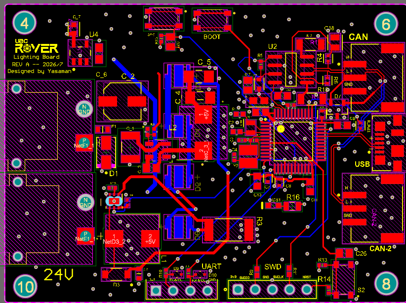
Rover lighting PCB routing
PCB routing during layout development.
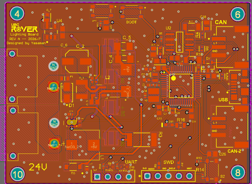
Rover lighting PCB polygon pours
Power and ground copper planning across the four-layer board.
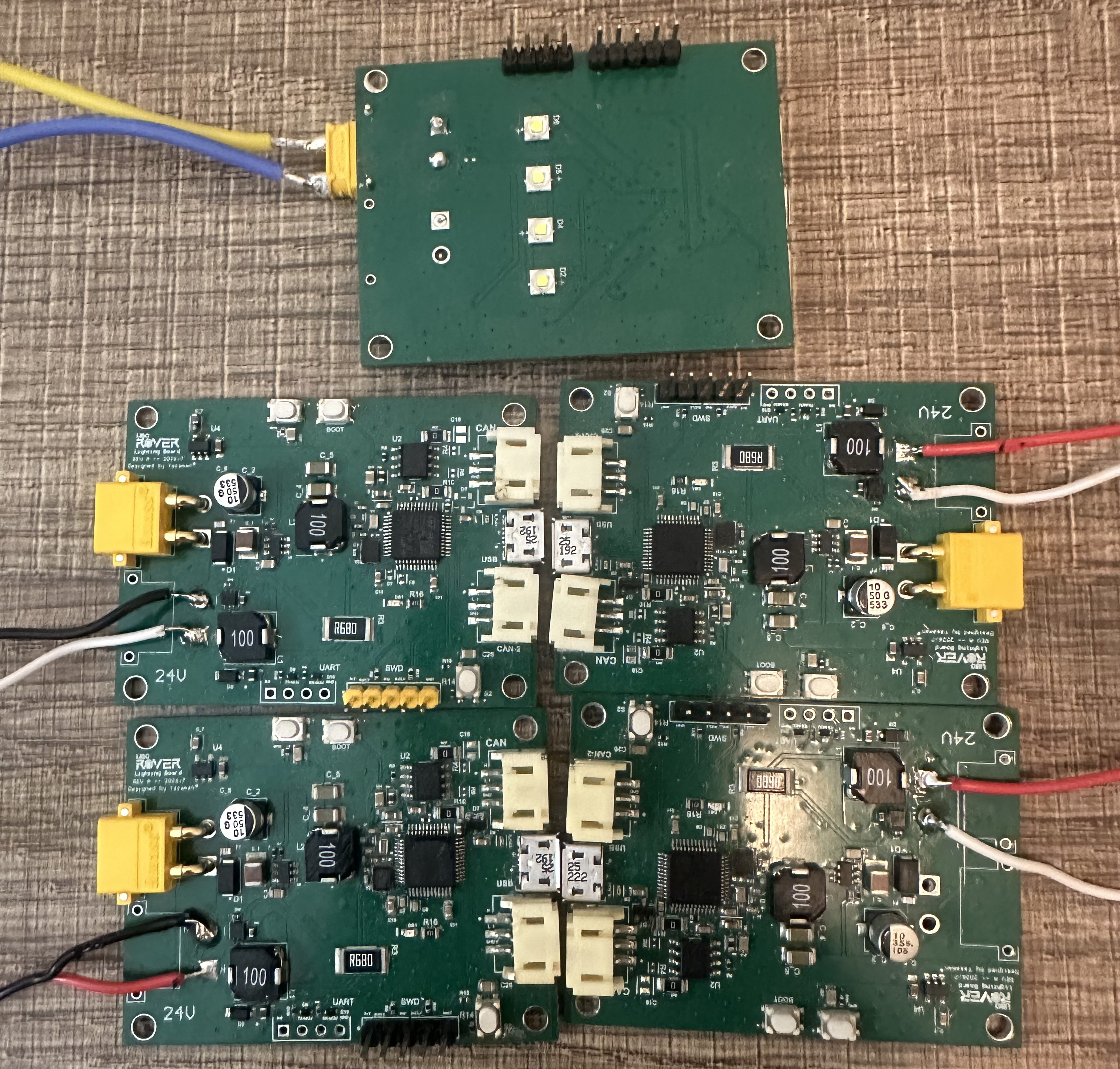
Five assembled rover lighting boards
Five assembled controllers after board bring-up and programming.
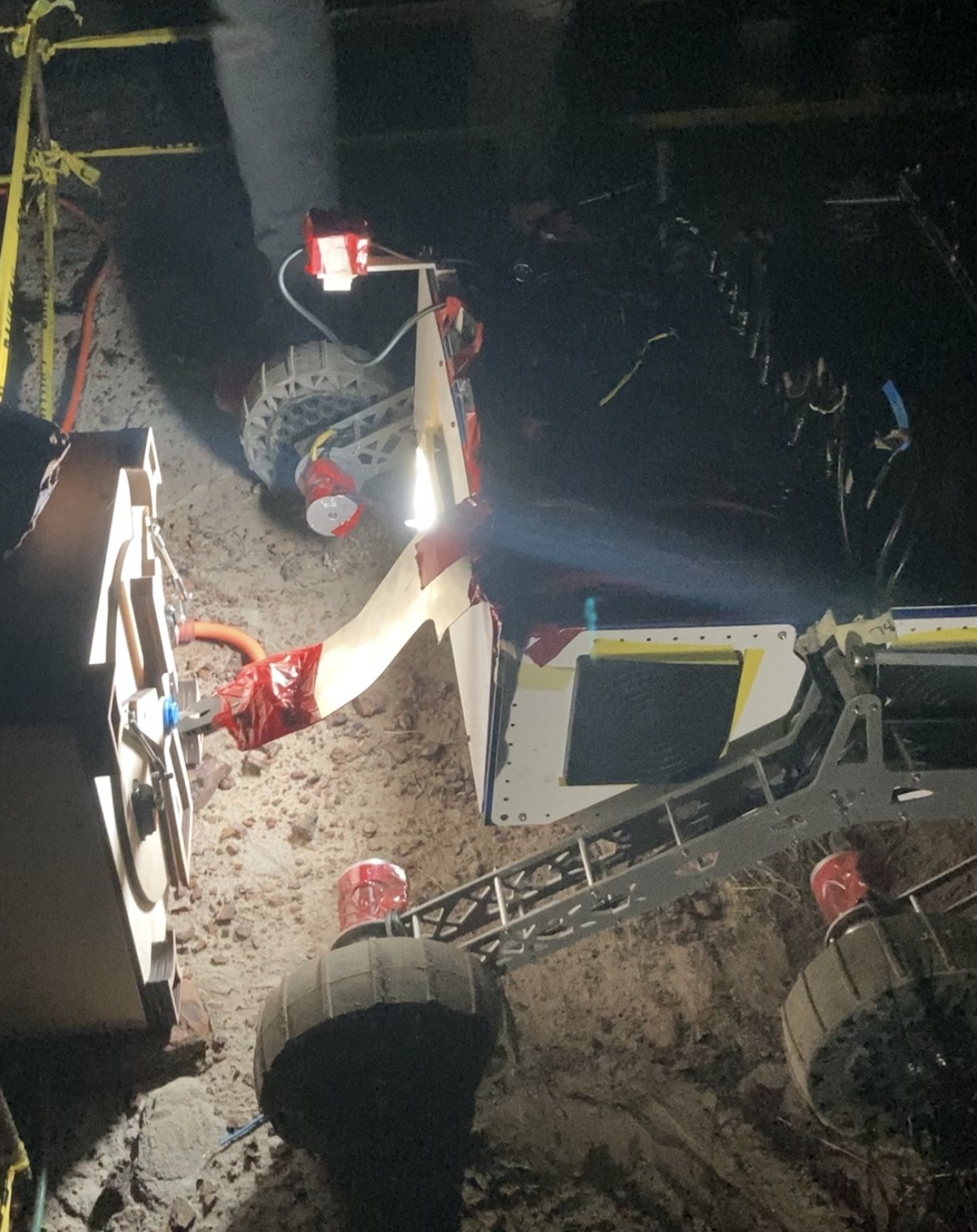
Lighting controller integrated onto rover
Lighting hardware integrated onto the rover for system-level testing.

Board Bring-Up & CAN Testing

I validated the boards using a bench supply, USB-CAN interface, STM32 firmware, and Python tooling before integrating them into the rover.

01

System Ownership

I owned the lighting-controller subsystem from the initial electrical design through final rover integration. The controller needed to accept the rover power-bus voltage, generate the required low-voltage rails, drive the LEDs, communicate over CAN, and support firmware-controlled lighting behavior.

My work included component selection, schematic design, PCB layout, assembly, STM32 programming, CAN integration, board bring-up, debugging, and system-level testing.

Hardware

PCB & Power Design

Custom four-layer controller with power conversion, LED driving, STM32 control, CAN, protection, and programming interfaces.

Firmware

STM32 Control

PWM lighting control, CAN command handling, feedback, heartbeat behavior, and simultaneous communication.

Assembly

Five Boards

I assembled, reworked, brought up, programmed, and validated five copies of the controller.

Integration

Rover Deployment

Final controllers were integrated into the rover electrical system and controlled through the rover CAN network.

02

Power Architecture

The rover power bus ranges from approximately 21 V to 29.4 V. The lighting board therefore needed to tolerate the full operating range while generating stable rails for the LED driver, MCU, and communication electronics.

Power Input
Keyed XT30 connectors provide the board power interface from the rover power distribution system.
Input Protection
A 1 A fuse and TVS protection provide input fault and transient protection.
5 V Rail
An LMR51420 switching regulator converts the rover battery input to a regulated 5 V rail.
3.3 V Rail
A TPS7A2033 LDO generates the 3.3 V rail used by the STM32 and low-voltage logic.
Current
During full-PWM operation the complete board drew approximately 0.75 A from the input supply during testing.
03

LED Driver Design

The lighting stage uses a dedicated boost LED driver so the board can drive a series LED string while controlling brightness through the driver control input.

LED Driver
KTD2505R boost LED driver.
Inductor
10 µH inductor in the boost power stage.
Current Sense
A 0.6 Ω sense resistor sets the LED current.
LED String
Four high-brightness LEDs are connected in series on the board.
Brightness Control
The STM32 uses PWM through the driver's control input to adjust lighting intensity and implement lighting patterns.
04

STM32 & CAN Interface

An STM32F103C8T6 provides the local control logic. The board includes the MCU support circuitry, programming interface, UART/USB access, timing components, and CAN transceiver required for integration with the rover network.

Microcontroller
STM32F103C8T6 with local decoupling, reset, boot configuration, and external clock circuitry.
Programming
SWD header and ST-Link were used for firmware flashing and debugging.
CAN Transceiver
TCAN334G provides the physical-layer interface to the rover CAN bus.
CAN Protection
ESD protection is included at the external CAN interface.
Termination
Split termination uses two 60 Ω resistors with a 4.7 nF midpoint capacitor. Termination is populated only when the board is used at a bus endpoint.
05

Four-Layer PCB Layout

I designed the PCB in Altium as a four-layer board. The layout needed to accommodate switching power conversion, the LED boost stage, the MCU, CAN communication, and high-current power paths on a compact board.

Layer Stack
Top signal and component layer, solid internal ground plane, internal 3.3 V plane, and bottom signal layer.
Switching Loops
Switching components were placed closely to reduce high-current loop area and keep switching nodes compact.
Power Routing
VIN, 5 V, and other higher-current paths use wider copper and local pours.
Sensitive Circuits
MCU, crystal, feedback, and CAN circuitry were kept away from the highest-noise switching regions where practical.
Grounding
A continuous internal ground plane provides a low-impedance return path across the board.
06

Assembly & Hardware Bring-Up

I assembled five boards using a solder-paste stencil, reflow, hand soldering, and hot-air rework. Bring-up was done incrementally so I could confirm the power rails and MCU before moving on to communication and LED testing.

This was my first PCB revision and I did not need a board respin. After assembly I was able to bring up the power rails, program the STM32, get CAN communication working, control the lighting, and later use the same hardware on the rover.

First revision used on the rover

The original fabricated PCB progressed through bring-up, firmware development, CAN validation, and final rover integration without requiring a second board revision.

07

Firmware & CAN Communication

I used STM32CubeMX and STM32CubeIDE to configure the MCU peripherals and develop the lighting firmware. The final firmware integrated the lighting board into the rover's existing communication architecture.

I added the lighting-specific CAN message packing and parsing, message types and lengths, command handling, feedback behavior, heartbeat communication, and support for simultaneous receive and transmit operation.

STM32
Firmware developed in C using STM32CubeMX and STM32CubeIDE.
PWM
Timer PWM controls LED intensity and lighting patterns.
CAN Commands
CAN messages control lighting behavior and allow board status and feedback to be communicated.
Python Testing
Python with python-can and gs_usb was used with a USB-CAN adapter to transmit and inspect CAN traffic during bench validation.
08

Rover Integration

After bench validation, the controllers were installed on the rover and integrated with the rest of the electrical system through CAN.

The firmware supported direct brightness control as well as system behaviors such as Morse-code lighting and dynamically adjusting lighting based on rover conditions, including proximity to obstacles.

This stage was important because it moved the project from a working PCB on the bench to a subsystem operating as part of a larger mobile robotic platform.

09

Tools & Skills

This project combined PCB design, embedded firmware, power electronics, communication interfaces, assembly, bring-up, debugging, and rover-level system integration.

Altium Designer STM32F103 STM32CubeMX STM32CubeIDE C Python CAN 2.0 USB-CAN PWM UART SWD ST-Link Buck Converter Boost LED Driver LDO CAN Transceiver TVS Protection 4-Layer PCB Reflow Hot-Air Rework Soldering Oscilloscope DMM Bench Power Supply Hardware Bring-Up Circuit Debugging