Robotics | Electromechanical Design | System Integration

Robotic Piano Actuation System

This was a course group project. My contribution centered on the electromechanical actuation and physical integration of the robotic hand. I machined solenoid components, wound and tested the electromagnetic coils, iterated the finger linkage geometry, soldered and managed actuator wiring, integrated the moving hand assembly, and developed the Python positioning model used to calculate carriage positions across all 54 piano keys.

Course Group Project Completed
54 piano keys
5+ mechanical iterations
12 V actuator drive
30 AWG magnet wire
15-20 Ω coil design range
0.6-0.8 A electrical range

Integrated Robotic Piano

Complete integrated robotic piano system
Complete system after mechanical, actuator, wiring, carriage, and system integration.

Building the Actuation System

The actuation system went through repeated cycles of CAD, machining, coil winding, resistance measurement, FDM printing, soldering, wire routing, mechanical assembly, and physical testing before the final system came together.

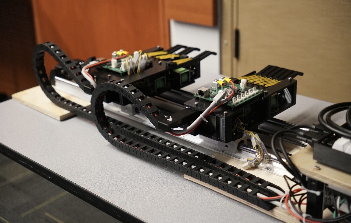
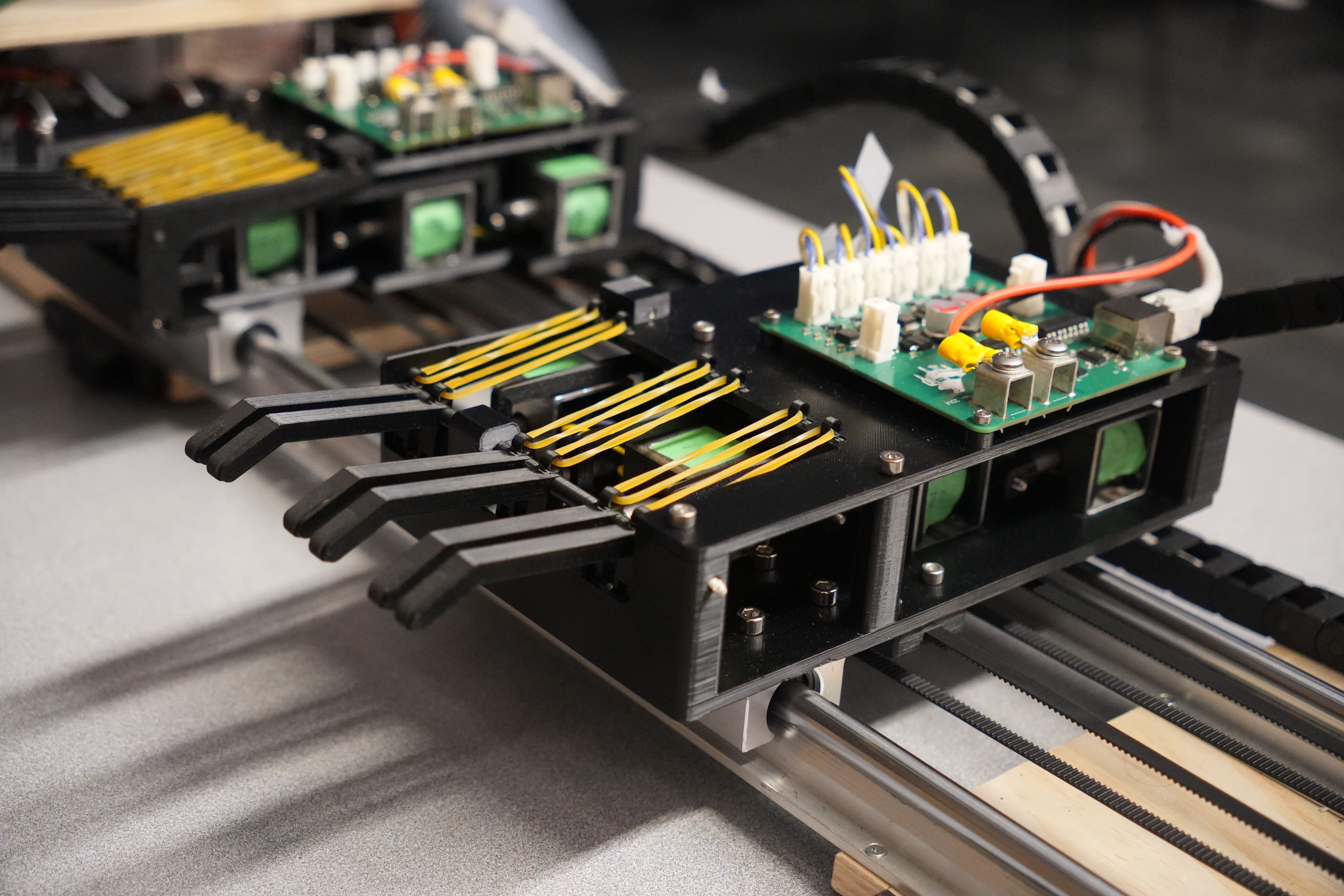
Integrated robotic piano hand
Integrated robotic hand assembly mounted on the linear carriage and rail system.
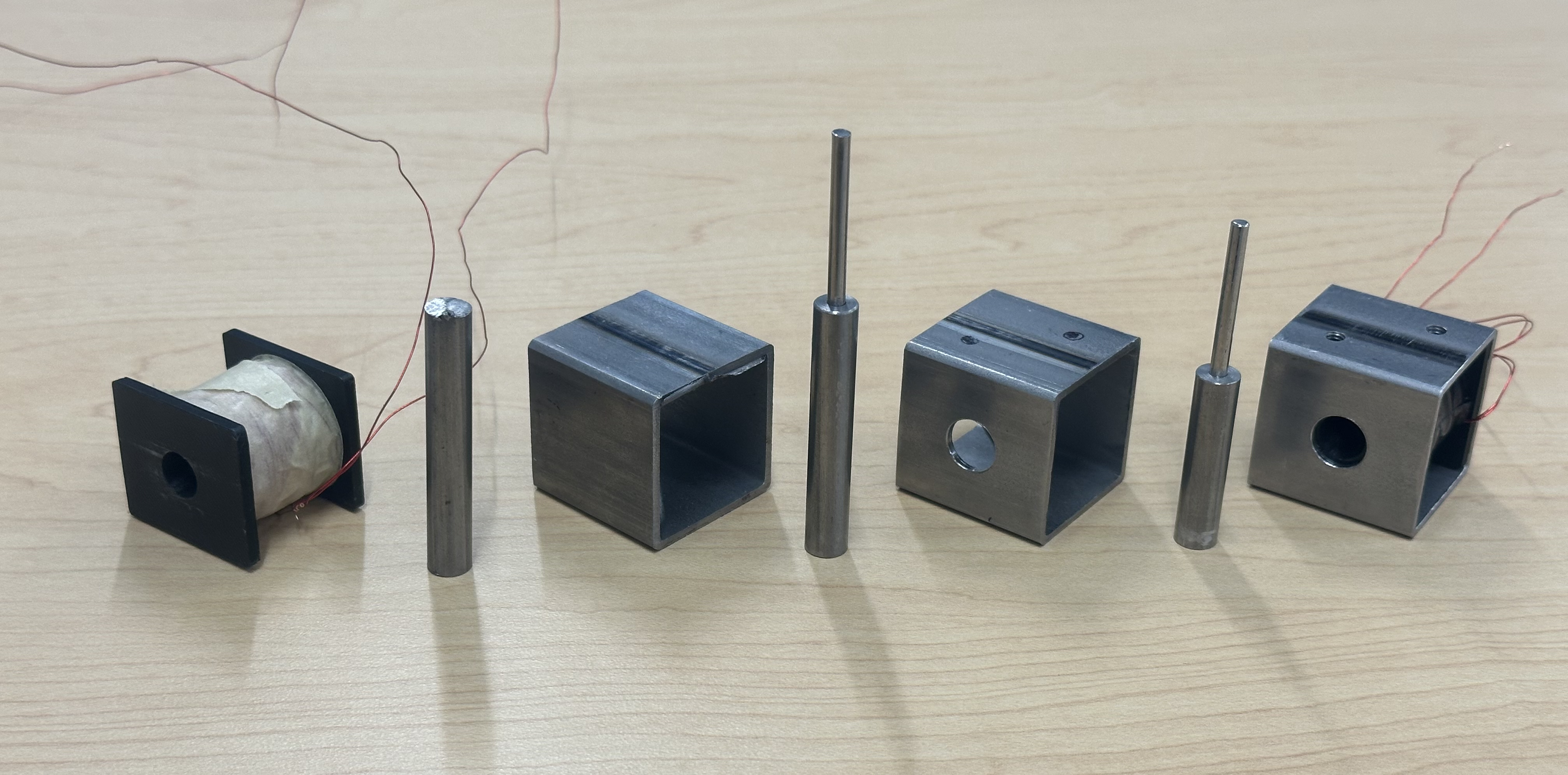
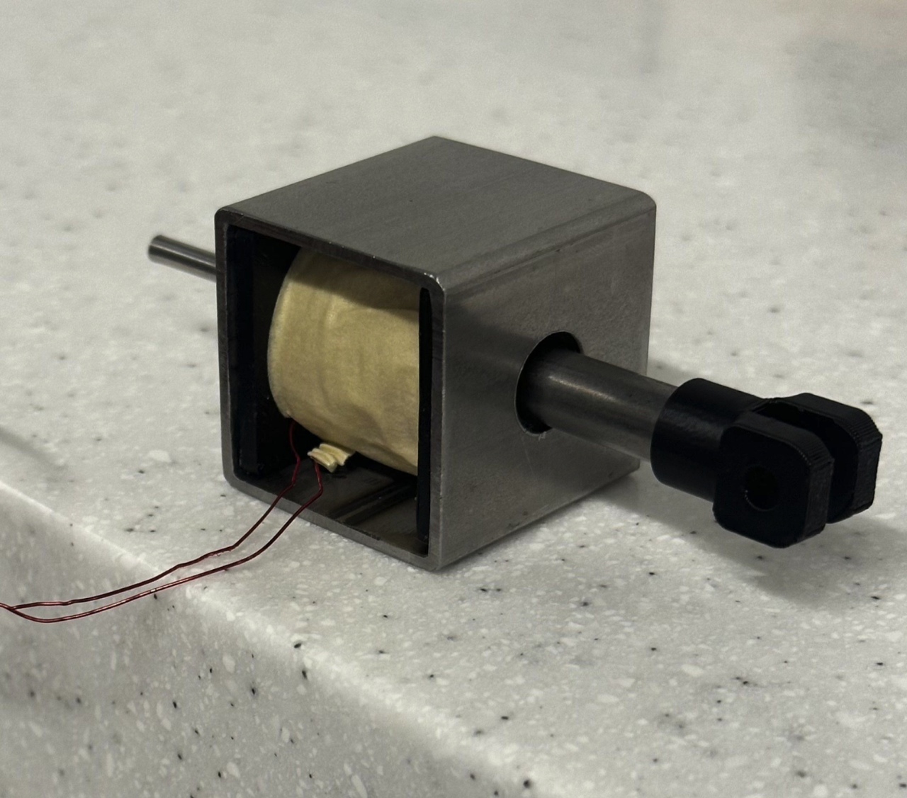
Machined solenoid components
Solenoid fabrication in progress. I machined the metallic housings and plunger components using the lathe and milling machine as one of two team members certified and authorized to machine metallic parts.
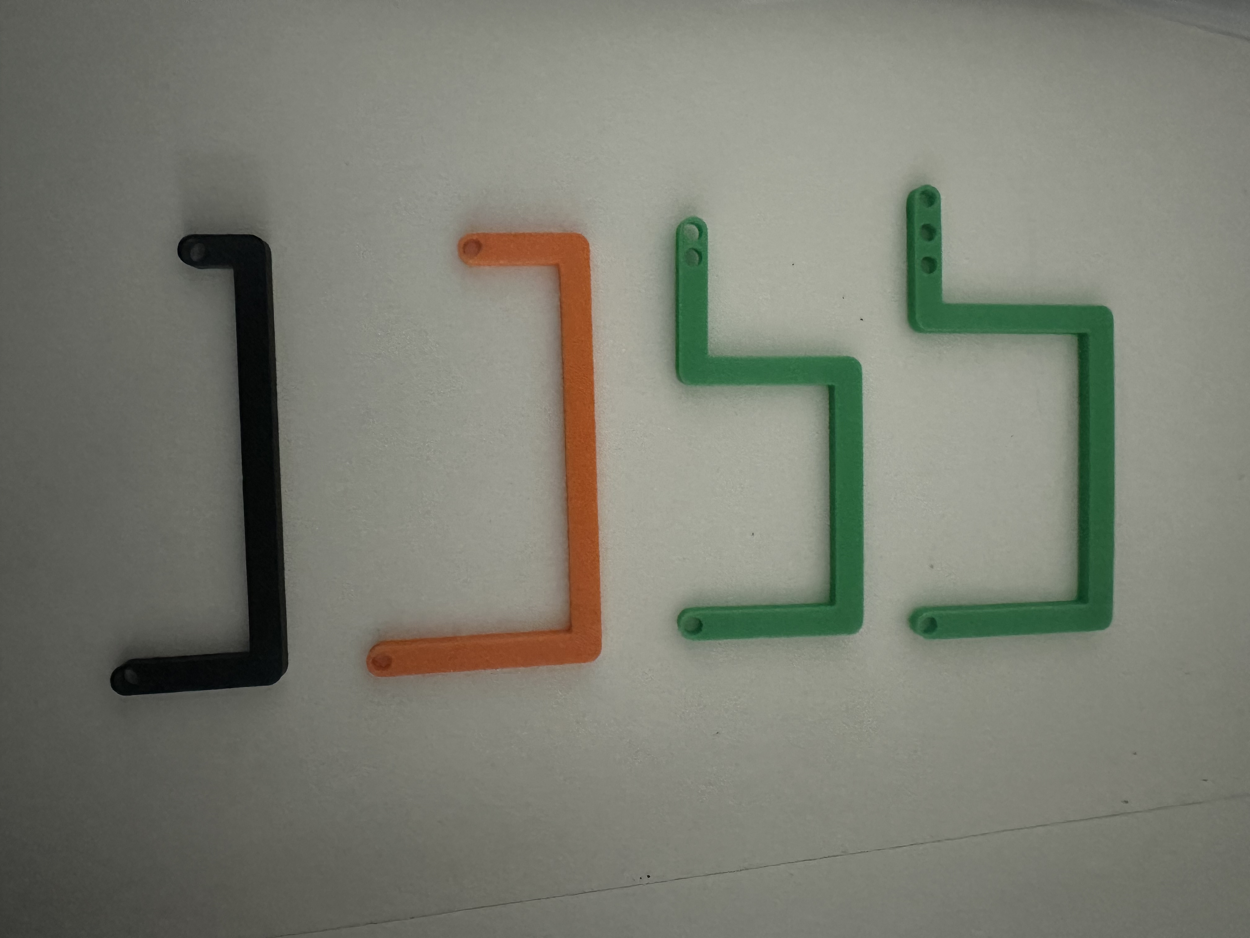
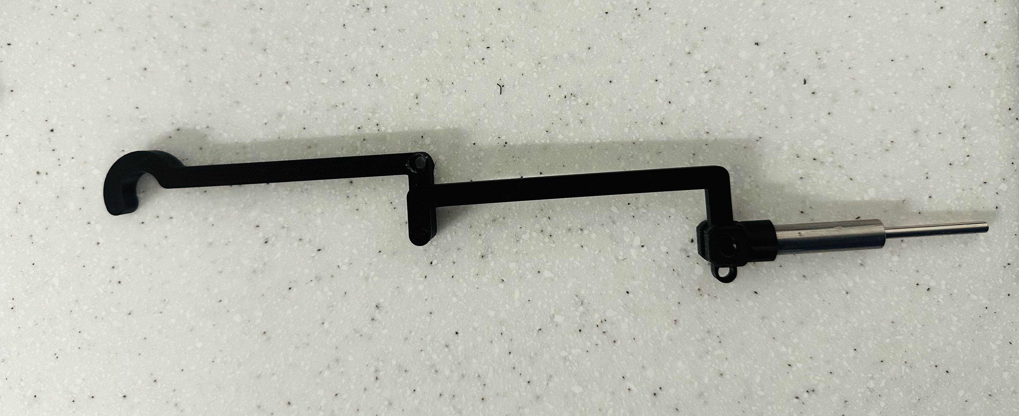
FDM finger joint iterations
FDM finger-joint iterations. I changed linkage length, mounting position, and geometry in small increments to improve alignment, reduce the actuator gap, and obtain stronger and more repeatable key actuation.
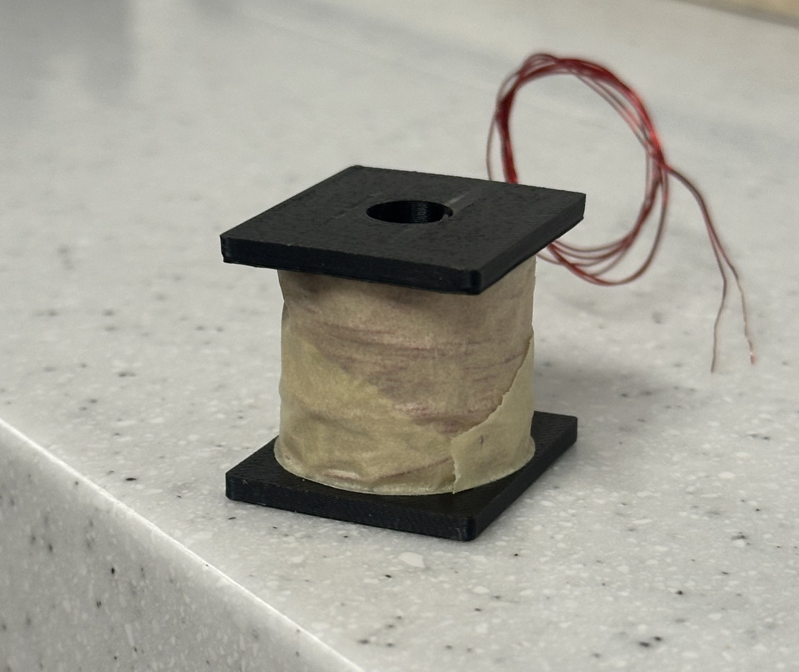
Solenoid coil wound using 30 AWG magnet wire
Solenoid coil wound with 30 AWG magnet wire. I checked resistance throughout the winding process because coil resistance directly determined current draw from the 12 V actuator supply.
Solenoid attached to robotic finger linkage
Solenoid plunger and finger linkage fitted and mechanically fastened together before installation onto the hand base.
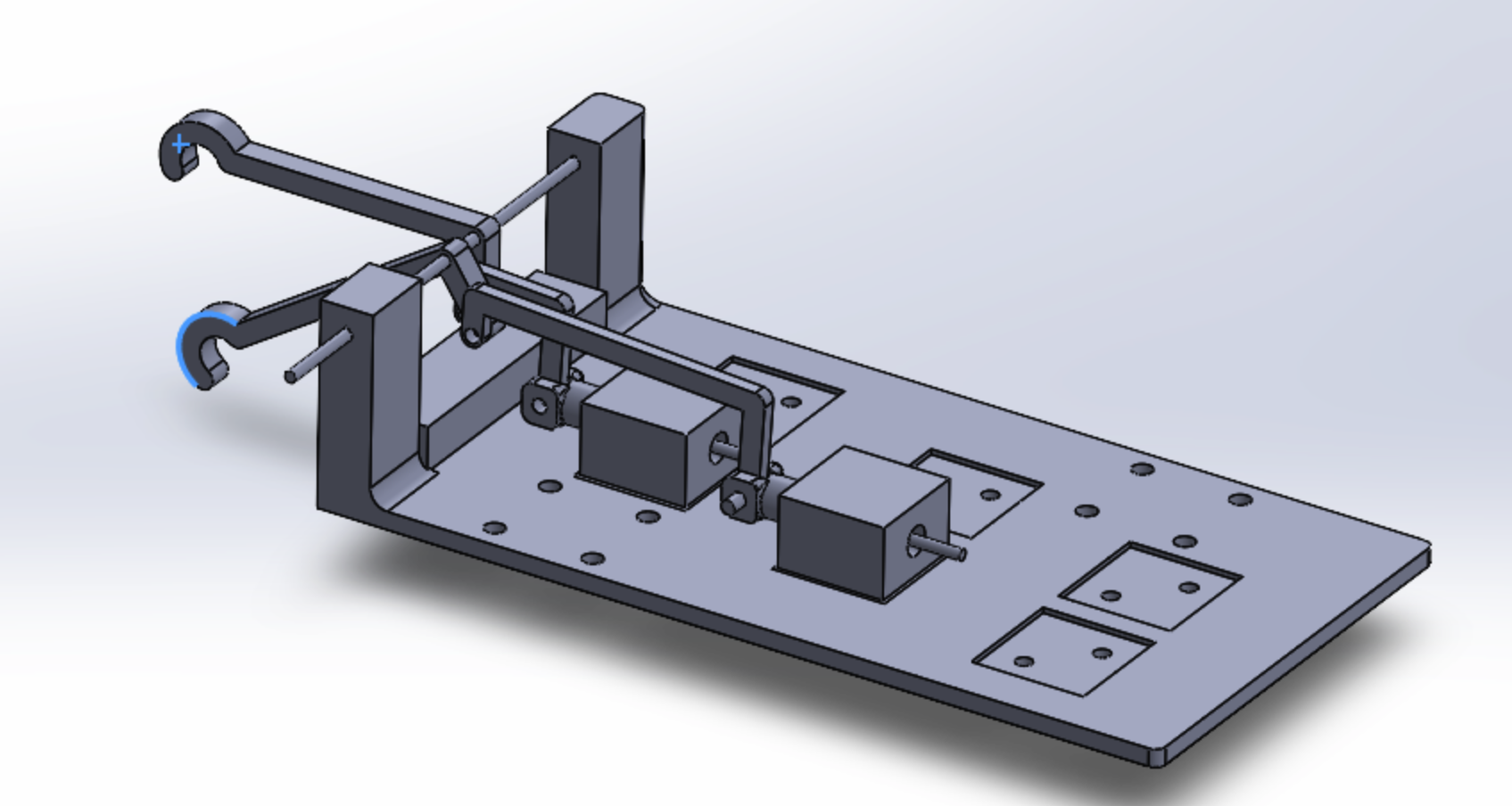
SolidWorks robotic piano carriage assembly
SolidWorks development of the mechanical carriage and actuator structure.
Early custom solenoid actuator prototype
Earlier custom solenoid and mechanical prototype during subsystem development.
Robotic piano mechanical linkage development
Mechanical linkage and actuator-integration development.

Complete Robotic Piano System

The final integration brought together the machined solenoids, printed finger linkages, carriage mechanics, actuator wiring, electronics, and positioning system.

Complete integrated robotic piano demonstration
01

My Contribution

My work covered the actuation path from the electromagnetic actuator itself to the mechanical finger, wiring, moving carriage, and final physical integration.

A large portion of the work happened through repeated lab sessions. Changes to the solenoid or linkage often affected wiring, clearances, force transfer, and assembly, so I moved repeatedly between machining, winding, resistance measurement, printing, soldering, integration, and testing.

Electromagnetic

Solenoid Development

Magnetic housing, plunger, coil winding, resistance, current draw, actuator gap, and electromagnetic-force development.

Fabrication

Machine-Shop Work

I machined metallic actuator components using the lathe and milling machine as one of two team members authorized to machine metallic parts.

Mechanical

Finger Iteration

Multiple FDM revisions were tested to improve actuator position, alignment, mechanical force transfer, and key contact.

Integration

Wiring & Assembly

Actuator wiring, soldering, harness routing, mechanical assembly, and moving-system clearance were integrated and tested together.

02

Electromagnetic Solenoid Design

The solenoid had to be treated as an electromagnetic and mechanical system together. Magnetic materials, coil winding, the 12 V supply, current draw, actuator gap, plunger travel, and linkage geometry all affected whether the finger could press a key reliably.

The air gap was especially important because air has much lower permeability than the steel magnetic path. Even a relatively small gap can contribute strongly to the magnetic reluctance of the system. Reducing unnecessary separation between magnetic components therefore became one reason for repeatedly iterating the finger geometry and actuator placement.

Housing
A mild-steel housing was used so the housing could form part of the low-reluctance magnetic flux path.
Plunger
The mild-steel plunger formed the moving magnetic component and translated electromagnetic force into mechanical motion.
Guide Rod
304 stainless steel was used for mechanical guidance rather than as a major component of the magnetic flux path.
Coil
30 AWG insulated magnet wire was wound around the bobbin, with resistance measured throughout the winding process.
Electrical Range
The actuator was designed around a 12 V supply. A 20 Ω coil draws approximately 0.6 A, while a 15 Ω coil draws approximately 0.8 A. Coil resistance therefore directly constrained current draw and heating.
Mechanical Coupling
Linkage geometry and actuator placement were adjusted together to improve force transfer, alignment, and actuator spacing.
Electrical and mechanical design were coupled

Increasing current was not the only way to improve actuation. Mechanical geometry, air gap, magnetic materials, and the way force was transferred through the linkage all affected final key-press performance.

03

Machining & Fabrication

I was one of two members of the course team who were certified and authorized to machine metallic components in the machine shop. This made actuator fabrication one of my main responsibilities during the build.

I used the lathe and milling machine to fabricate and finish the metallic solenoid components, including the housings and plungers. The finished parts then had to mate with the printed bobbin, guide hardware, linkage, mounting hardware, and hand base.

Housing Material
1.25-inch mild-steel square section with approximately 0.065-inch wall thickness.
Plunger
5/16-inch mild-steel rod machined for the electromagnetic actuator.
Guide Rod
1/8-inch 304 stainless-steel rod used for mechanical guidance.
Fabrication Loop
Machining was followed by fit checks, mechanical assembly, coil installation, actuator testing, and additional revisions where necessary.
04

Finger & Linkage Iteration

The electromagnetic force generated by the solenoid still had to be transferred through the finger mechanism to the piano key. I therefore treated the mechanical linkage as part of the actuator system rather than as an independent component.

Multiple finger and joint revisions were printed with changes in linkage length, mounting position, and geometry. Some dimensions were changed in approximately 1 mm increments so I could compare the physical behavior of closely related designs.

Link Length
Different linkage lengths changed both the resting actuator position and the resulting key-contact geometry.
Mounting Position
Mounting points were moved between revisions to improve actuator alignment and mechanical motion.
Actuator Gap
Linkage geometry was also used to reduce unnecessary spacing in the magnetic actuator path.
Physical Testing
FDM printing made it possible to test several closely related geometries quickly on the real piano mechanism.
05

Wiring, Soldering & System Integration

Once the individual actuators worked, the harder problem became integrating them into a moving system. The carriage contained mechanical joints, solenoids, wiring, drive electronics, structural parts, and rail interfaces in a limited amount of space.

I worked on actuator wire routing, harness organization, soldering, and mechanical integration. Wiring had to remain clear of the finger joints and moving hardware while still allowing the carriage to travel along the keyboard.

Integration was iterative. Whenever the geometry or actuator position changed, I often had to re-check wire routing, soldered connections, clearances, and mechanical movement before testing the system again.

Harness Routing
Actuator wiring was organized so the bundle could move with the carriage without interfering with the fingers or rail mechanism.
Soldering
Coil leads and actuator connections had to remain electrically reliable while being integrated into a mechanically moving system.
Mechanical Clearance
Wiring, solenoids, fasteners, finger linkages, and structural parts were checked together for physical interference.
Final Integration
Actuator, finger, harness, carriage, electronics, and positioning behavior were tested together as one electromechanical system.
Integration was a major part of the project

A working solenoid or finger by itself was not enough. The actuator, linkage, wiring, carriage, electronics, and positioning system all had to work together without interfering with one another.

06

Key Positioning Model

I developed a Python positioning model using keyboard geometry, gear pitch, tooth count, and a calibratable hardware offset to calculate carriage positions across all 54 piano keys.

The script converts the physical position of each key into the motor-coordinate units used by the carriage. This provided a systematic way to generate the complete key position table rather than calibrating each location independently.

Python
Piano Key Position Mapping
key_positioning.py
import math

PITCH = 2.0
TEETH = 39

MM_REV = TEETH * PITCH

MILLIRAD_REV = 2.0 * math.pi * 1000.0

TICKS_PER_MM = MILLIRAD_REV / MM_REV

OFFSET_TICKS = 0

NATURAL = 22.25
OCTAVE = 7 * NATURAL

CENTER = {
    'C': 0.5,
    'C#': 0.95,
    'D': 1.5,
    'D#': 2.05,
    'E': 2.5,
    'F': 3.5,
    'F#': 3.93,
    'G': 4.5,
    'G#': 5.0,
    'A': 5.5,
    'A#': 6.07,
    'B': 6.5
}

NOTES = [
    'C', 'C#', 'D', 'D#',
    'E', 'F', 'F#', 'G',
    'G#', 'A', 'A#', 'B'
]

NUM_KEYS = 54

keys = []

for i in range(NUM_KEYS):

    octave_index = i // 12

    note = NOTES[i % 12]

    mm = (
        octave_index * OCTAVE
        + CENTER[note] * NATURAL
    )

    keys.append(mm)


for i, mm in enumerate(keys):

    ticks = round(
        mm * TICKS_PER_MM
        + OFFSET_TICKS
    )

    comma = "," if i < NUM_KEYS - 1 else ""

    print(
        f"    {ticks:<8}{comma} [{i}]"
    )
07

Complete System Integration

The final system combined the custom electromagnetic actuators, printed finger joints, carriage structure, wiring, soldered actuator connections, drive electronics, linear motion system, and key-position model into one working robotic piano platform.

The carriage was not restricted to a single octave. The positioning system allowed the hand assembly to travel across the keyboard so the mechanism could reach all 54 mapped keys.

08

Tools & Skills

This project combined electromagnetic design, fabrication, mechanical prototyping, programming, soldering, and electromechanical system integration.

SolidWorks Python Electromagnetic Actuation Solenoid Design 30 AWG Magnet Wire Magnetic Circuits Machine Shop Lathe Milling Machine FDM 3D Printing Rapid Prototyping Mechanical Design Wire Harnessing Wire Management Soldering Electromechanical Integration Robotics System Integration